
Circuit Patterns, Part 2: Voltage Dividers
Pretty much any time you see two resistors connected in series with a wire coming out from between them, you are witnessing a voltage divider in action.In yesterday’s installment, we talked about the importance of circuit patterns, both for understanding the circuit schematics that you might find on the web and for building your own circuits. This series introduces some of the commonly used circuit patterns that are essential to electronics.
The first installment covered the most basic resistor pattern, the current limiting resistor. In this article, we are going to look at another basic resistor pattern the voltage divider.
Voltage dividers work because resistors, while they limit current, also eat up excess voltage. An LED, for instance, will tend to only eat up a few volts. The excess voltage left over will quickly lead to an overabundance of current. That is why, to work properly, LEDs generally require a current limiting resistor to “soak up” all remaining voltage.
If you place a resistor between two fixed voltages (such as the positive and negative terminals on a battery), the voltage across that resistor will be the same as the voltage across those terminals. If you have two resistors, each with the same value, in series across the terminals, each resistor will have half the voltage. If you are not familiar with the term “in series”, see my book Electronics for Beginners. In short, it means they are connected end-to-end).
If you take a wire and connect it between your two resistors, the voltage at that point in the circuit will be halfway between the source voltage (the battery voltage if connected to the positive battery terminal) and the destination voltage (zero if connected to the negative battery terminal). Thus, the two resistors divide the voltage, and that wire is now sitting in the middle of that voltage.
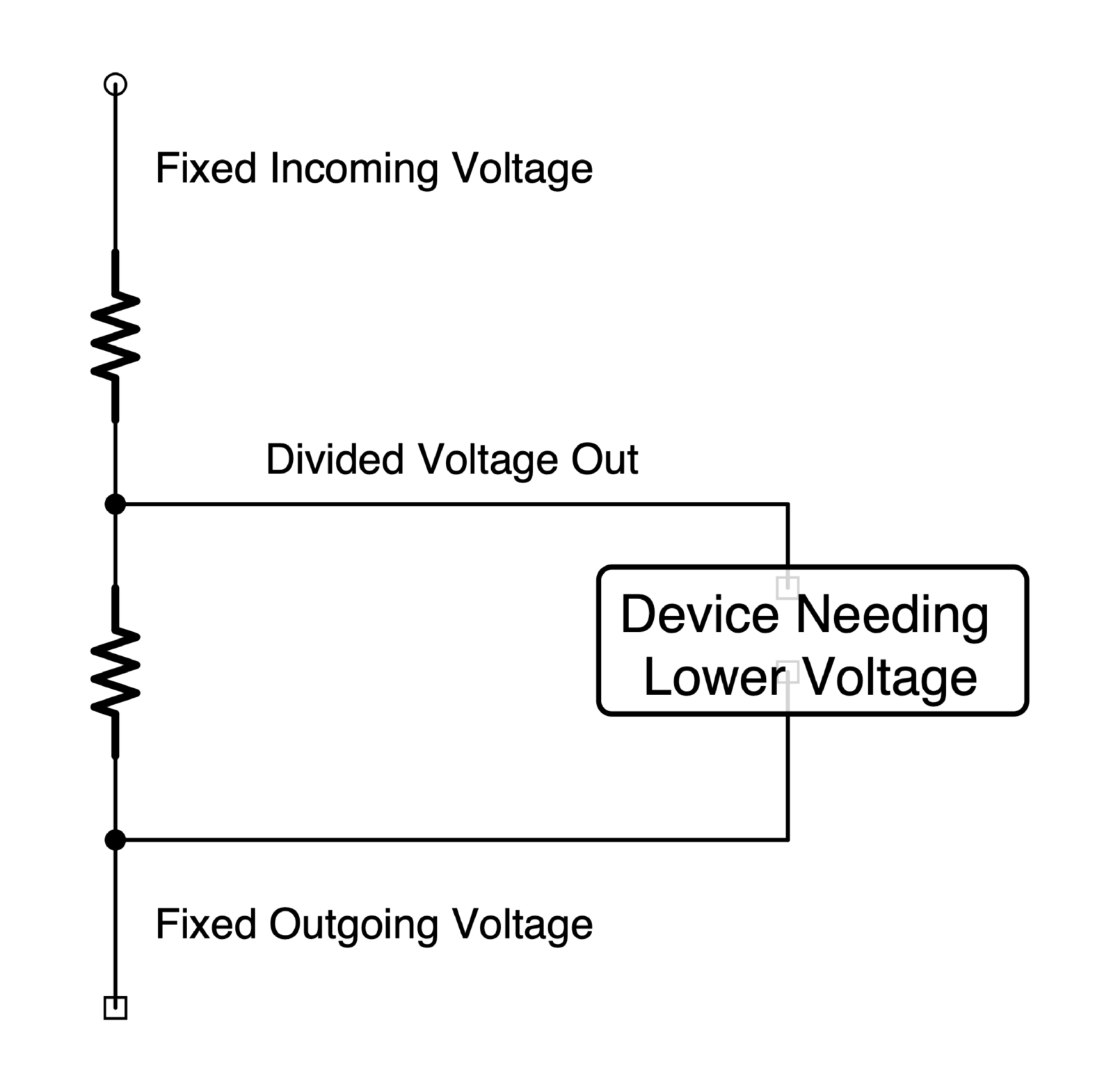
You can now connect a device in parallel with the bottom resistor and that device will operate at the same voltage as the bottom resistor.
What if we want a voltage other than the halfway point between our incoming and outgoing voltage? The ratio of the resistors will tell you the ratio of the voltage being consumed by each resistor. Therefore, if we want the device to be powered at one third of the incoming voltage, then we make the bottom resistor one third of the total resistance of both resistors.
Now, there are several caveats to this process which may limit either the design of the voltage divider or the ability to use a voltage divider at all. The first is the resistance (or current usage) of the device connected to the voltage divider. For a voltage divider to work properly, the device must use significantly less current (or have significantly more resistance) than the bottom resistor with which it is in parallel. By “significantly,” we usually use about 10x the resistance as a good starting point.
So, if you know the resistance of your device, divide that by ten to get the value of the bottom resistor. Then, figure out the ratio you need for the other resistor, to get your desired voltage.
The other caveat is that sometimes devices require too much power for a voltage divider to work at supplying them with the current. If your voltage divider must have less than 350 ohms of resistance, you probably need a different solution. Below that, not only will a voltage divider waste a lot of electricity, you can easily go beyond the power limitations of your resistors.
In any case, knowing about voltage dividers will not only help you with your own projects, it will help you recognize this pattern on schematics you might find on the Internet. Pretty much any time you see two resistors connected in series with a wire coming out from between them, you are witnessing a voltage divider in action.
.
To learn more about the basics of voltage, current, resistance, power, circuit patterns, and more, have a look at my new book, Electronics for Beginners: A Practical Introduction to Schematics, Circuits, and Microcontrollers, published by technology publisher Apress (a Springer Nature company).
Here’s “Circuit Patterns, Part I: Understanding circuit schematics.” You will get on much better in electronics if you learn to see the schematic line drawings as a series of patterns. When you begin to see the drawings in books on electronics as a connected series of familiar patterns, the world of electronics opens up.
You may also want to have a look at:
New electronics book honors citizen scientist Forrest Mims III
Jonathan Bartlett’s dedication reflects Mims’ immense influence on electronics enthusiasts—including himself, as a boy. Electronics for Beginners follows in Mims’ footsteps as it shows the budding electronics enthusiast the many new components now available and how to use them.