
Circuit Patterns, Part I: Understanding Circuit Schematics
You will get on much better in electronics if you learn to see the schematic line drawings as a series of patternsWhen I was young, I wanted to learn how to build electronics. I bought a large number of books from Radio Shack and read them all, cover to cover. Unfortunately, the books that I read helped me to understand a little bit about the periphery of electronics but not the core subject. I learned what each type of part did in general resistors, capacitors, transistors, inductors, etc., but I never really understood how all of the pieces fit together. How do you go from understanding the parts to understand how they fit together into a circuit?
Throughout my life, I have returned to electronics now and again, sometimes personally, sometimes professionally. I eventually learned that most electronics follows basic patterns that are used over and over again. In fact, schematics (line drawings that show the basic parts of a system) are usually a combination of just a few patterns plus a sort of connect-the-dots between major components. Most schematics, far from being cryptic, turn out to be pretty straightforward once you learn the patterns.
Building circuits is often straightforward as well. If you need to interface two components, usually one of the standard circuit patterns is all you need. Not everything falls quite so neatly into standard patterns; there are indeed some advanced patterns that are more complicated than the others. Nonetheless, you may be surprised to learn what you can do, knowing only the most basic ones—and how many circuit schematics only use those basic patterns, even in professionally designed electronics.
Unfortunately, very few books actually teach these patterns as patterns. That is, occasionally, they will point to some of the patterns as interesting uses of components but they will rarely ask you to think about circuits in terms of the patterns. However, once you do think about them that way, the world of electronics opens up. You start to see the patterns everywhere.
When I learned how to read schematics, I was still mystified by most circuits. Circuits usually consisted of a dizzying array of resistors with a few other components added in. What were all these resistors doing? Why were they there? How did someone figure out what values they should have? However, once I learned the basic resistor patterns, it started becoming immediately obvious what most circuits were doing and why.
For example, “Oh, that’s just a pull-down resistor.” “Looks like they are using a voltage divider there.” Once you understand the basic patterns, then circuits stop looking like a randomly-assembled group of parts that someone got lucky with and start looking like rational, well-ordered systems.
Resistors, for example, feature four basic resistor patterns: current limiters, voltage dividers, pull-up resistors, and pull-down resistors. These patterns form the bulk of the ways you will see resistors used in schematics. Whether you understand them will determine whether you understand circuits.
The first pattern we will look at is the simplest one, the current limiting resistor:
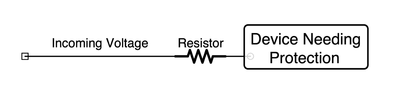
A current limiting resistor is simply a resistor that protects another component from being overwhelmed with current. Many devices, such as LEDs, are limited as to how much current can flow through them without breaking. Thus, a current limiting resistor limits how much current will flow through that part of the circuit.
How big should you make a current limiting resistor? That can be determined using Ohm’s Law. In general terms, if we know the voltage coming in, we can use Ohm’s Law to figure out the maximum current the resistor will allow. To simplify matters, we will ignore other contributing factors for now.
Ohm’s Law states that our circuit’s resistance should be the voltage divided by the desired current. We can use this as a starting point for the value we choose for the resistor. If we place a resistor with that value in series with our component, it will offer the component the desired current protection.
In Part 2, we will look at the next resistor pattern, the voltage divider.
If you are interested in circuits and how to build them, I hope you will also check out my book Electronics for Beginners: A Practical Introduction to Schematics, Circuits, and Microcontrollers, published by technology publisher Apress (a Springer Nature company).
If you don’t know what a resistor is, that’s okay. Electronics for Beginners walks you through the very basics and will introduce you to each of the main components commonly used for building circuits, what they do, and how they are used in practical circuits.
You may also want to have a look at:
New electronics book honors citizen scientist Forrest Mims III.
Jonathan Bartlett’s dedication reflects Mims’ immense influence on electronics enthusiasts—including himself, as a boy. Electronics for Beginners follows in Mims’ footsteps as it shows the budding electronics enthusiast the many new components now available and how to use them.